ШҜШіШӘЪҜШ§ЩҮ Ш¬ЩҲШҙ ШЁШұШ§ЫҢ ШӘШ№Щ…ЫҢШ...
ШҜШіШӘЪҜШ§ЩҮ Ш¬ЩҲШҙ ШЁШұШ§ЫҢ ШӘШ№Щ…ЫҢШұ ЩӮШ§Щ„ШЁ
Operating manual for mould repair welding machine
В 1. General
As the world industrial technology continuously developing, the industrial mould has been a main production tool in relevant industries. However, its few defects, damage and abrasion results in the whole set mould, even the whole equipment being disused, in term of this,В В В В В В В В В В В В В В В В В E-9188A(B) intelligent protection type mould repair welding machine developed by us enables your damaged or disused mould to be used again, it is the ideal tool for industrial mold with few defects, while, its virtues as follows:
- High strength of welding: the repairing place can be milled and filed.
- High accuracy of repair: repairing with slice can’t miss the original datum plane, end it uses little residua I welding material, easy for reshaping at late stage. The min repairing: 0,03mm (with 0.035 repair material).
- ‘Wide applicable range: the work piece made by kinds of metal material except for copper and aluminum of ultra-low resistance rate can be repaired,
- Little damage of basic material: due to little heating paint, the basic material can’t deform or anneal.
- Stable welding power when the Supply voltage is waved in the range of Вұ10%, the machine still can make sure inequality of repairing is stable.
- High output power: welding with single point, it can weld ОҰ1 mm wire
- Intelligent protection: protect against all Illegal operating and abnormal power supply, and prompt with alarm.
- Simple operating: can be operated workers of common level.
- Convenient electric connecting: ferromagnetic connector supplied that takes convenience for any work pieces to connect the power supply.
- Convenient carrying, small volume, light weigh;, the main machine is only 25kg or 20kg
В II. Performance index
Repairable material: kinds of metal material can be re paired except the material of ultra-low resistance rate such as copper and aluminum.
Repairable item:
В 1 .Defects occurring in processing, such as extreme cutting, much difference in sizes, damage edge angle, not enough argon welding.
2. Part abrasion produced in operating industrial mould.
IV. Working principle
Basic working principle of this machine: release the el act lie energy stored In capacitor into connecting place between workplace made up of metal material with high resistance rate like steel and repairing material, to make them weld together for rapid heating and get the aim af repairing the industrial mould. Because the heat happens in the small range (<1mma) far short time (grade ids), tha basic body of work piece can’t deform, anneal or change the color.
V. Protection system
The core of intelligent protection system adopts the modem microcomputer chip, through programming, it can protect against illegal operation for unskillful doing, ever high sup ply voltage, so that it can praventthe mould and machine being damaged, when the machine is turned onr it will make three short whistles and one long whistles, it shows that the protection system is normal.
VI.В Technology of repair
1. Selection of repairing material
There iВ» alloy steel (H08Mn2Si A}, stainless steel (lCr18Ni9Ti), spring steel (7 0#) supplied for repairing material I with the product. Alley steal h as fine binding force with most mould steels, its hardness of repairing point Is moderate (about 30HRC), and It is easy to reshape at last stage, because its color approximates to that of most mould steels, the trace of repairing is little, the repairing point can he treated with the bumt-out and azotizing technology. The stainless steel has fine anti- corrosion property, good binding force with kinds of material, the repairing material itself has good to ugliness (about 20HRC), however, it Is not suitable for module surface requiring burnt-out. Spring steel has excellent quench hardening property, the repairing place can quench by itself, so its hardness is very high (>50HRC), it is suitable for the module that has been quenched and needs to be quenched finally. 2.Selection of repairing material thickness
Selection of repairing material thickness is determined by module surface fineness and repairing range, if the module cavity requiring high fineness needs to be repaired, the thickness of repairing material shall be less than 0.12mm. The module, whose material has quench hardening property, but module cavity needn’t to be quenched; the thickness of repairing material required shall be less than 0.08 mm, so that it can reduce the trace caused by heating and harden quenching from welding basal body material of welding point outer ring.
3. Repairing
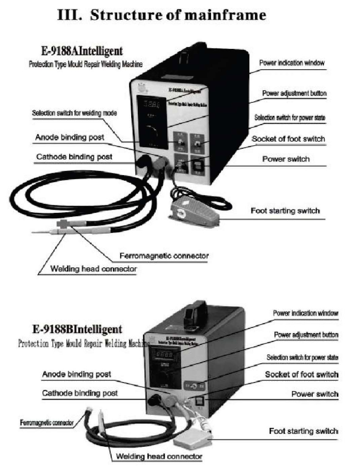
Connect wire: input AC 220V/50Hz commercial power; the wire of welding head is connected with anode binding post, ferromagnetic connector Is connected with cathode binding post, and attracted on the bright and rustles surface of work plots , The wire of fool switch is inserted into its socket. The screw of output binding post shall be tightened.
Clean surface and repair welding head
If there is oil stain on the repairing place, you can dear away with alcohol and acetone, the oxide film on it can be cleared away with abrasive cloth or abrasive stick, the anti-rust oil and oxide film on the repairing material also can be cleared away in this way. Enlarge the hole to the deep and small hole (pinpoint hole) and bluff hole, the methods as fallows: choose the power state at the precise place, make the welding mode in the state of connecting, adjust power indicate on value for a bout 500-700. use ball welding head (the size of welding head depends on the size of enlarging hole, in general, the welding headier 3- $5) to pre as on the hole, turn on the starting switch with foot, let the tip of hole wall fuse and change into a ball pit, so as to increase the welding face between repairing material and work piece. [Refer to following diagram), if the flaky small holes, you can grind away about 0.1mm thickness of surface with electric grinder.
Diagram for after enlarging hole and then repairing
The welding head is sorted in to two types; one is the round rod whose top is the half bail, we name it ball welding head, it can roll continuously and press welding on the repairing material, has stable contacting surface so as to make sure repairing quality, it is the welding head used most. The other is named plane welding head, it is specially manufactured for making up for the interior angle place that the ball welding head cant weld, us contacting pan of terminal is made into a plane usually. It is suitable for repairing the base angle place, f Refer to following diagram)
The contacting surface of plane welding head is 1-2mm best, if it Is too small, it will re suit in tip electric arc discharging and cause the work piece shows discharging pit. if It is too big. it will cause the false welding for lack welding power. Whichever welding head, all of them shall be corrected so as to make sure the contacting surface is smooth.
C, Power selection: the power size depends on the thickness of repairing material. The mating situation as shown following in table:
The data listed in the table is supplied for standard welding head (ОҰ5 half ball welding head). In general, the larger contacting are a between welding head and repairing material, the higher power required by repairing material. According to practical situation, user can increase and decrease the data referring to table 1.
Check if the power is proper for the repairing material by means of testing welding, try to weld the unimportant small part of the repairing material, then file the small part with file, if filing up to 1/2вҖқ thickness of repairing material, it has pit that may be caused by higher power or less contacting area of welding head, if the repairing material is finished filling, there will be stripping at the repairing part of welding , which indicates that the power is lower or the rolling is not even and the r a is welding missed.
Notice: During transferring the routine slate info precise stale, because the high voltage of energy stored capacitor cant step down at once, the machine win make the alarm for higher voltage. Just switch off the power, and then burr on the machine again after 2s,
D. Turn on machine: turn or the power switch of main machine, the power indicator lamp goes on, after making three short whistles and one long whistle. The system accesses to the stale of ready for repairing,
E Repair: the welding method that the welding head presses the repairing material firmly, stepping on the starting switch with the foot, there will be a welding spot. If the switch of welding mode la in the continuous position, stepping on the stalling switch with the foot, there will be continuous welding pulse, by means of rolling the welding head slowly, make 1he one welding spot close up to the another, thus the repairing material can be welded tightly on the work piece. The pressure for pressing work piece shall be proper, if the pressure is too little, it will lead that the welding head fails in contacting with repairing material and spark shows; if the pressure is too big, the welding efficiency reduces. The general repairing method as follows; Basing on choosing proper repairing material and power, select single point state for welding mode, locate the repairing material [dear away the anti-rust oil and Fran mat, If any) at the repairing place required with several welding spots, then select the continuous slate for welding mode, roll the repairing material evenly with the welding head. Pay attention that your don not have the welding head press the range beyond the repairing material, to prevent welding pit on the work piece. If you need multi repairing material to be used For increasing width or thickness, you can complete the operating with the same methods.
Notice: When repairing, please press the repairing material with the we4ding head, turn on the foot switch, after finishing repairing, please turn off the foot switch at first, then remove the welding head, otherwise, the operation would be illegal, the protection system would close, output and alarm, when the system accesses to the protection state, only turning off the foot switch, the system can exit the protection and enters into the monitor state again, in addition, when repairing, please wear the protection glasses, to prevent damaging eyes for high-temperature splashing material.
Causes of bad repairing and solutions:
CD Difficult to repair enough for the defect of edge an g I e: {exam pie: defect of edge angle before repairing is only 0,1mm, but it is still not enough given two-layer 0.1mm thickness.) The reason that the contacting area is quite small under the edge angle, and the welding power is higher, the repairing wilt be fused and ejected, the solution that you can reduce the welding power, change the welding part and direction of using force, keep away from the cusp of edge angle, weld on the both side, refer to following diagram.
Diagram of incorrect repairing edge angle Diagram of correct repairing edge angle
(2) Find m an y pin holes after finishing at repairing place: the reason as follows : В the welding power is too high or the contacting area between welding head and repairing material Ms too small (such as the welding head is too small or too tip), which causes the deforming of repairing is too large, besides, there are impurities II to a I r. ox I de layer, copper of welding he ad getting in the repairing material during rolling again and again. The solution as follows: repair with the thinnest repairing material sc that lower power can be used, deform of repairing: material can be reduced, make sure the purity of rep airing material, also get rid a of pinholes, (when welding again, please grind away 0.1 mm with electric grinder, then repair)
(3) There is seam or slim holes In the carter ring of repairing point: it is caused by two reasons, so you shall distinguish them. One reason: welding power is not enough, which leads the repairing material strips little, then, outer ring of repairing point shows circularity defect after being repaired and trimmed, however, the pit at edge is quite even before being repaired. Solution: you can increase welding power or reduce the thickness of repairing material, [if welding again, please clear away the original repairing material). The other reason: impurity such as the oxide layer on the work piece takes effect, the area welded is not enough during being repaired, and all defect parts haven’t been welded, then, the bluff holes or pits at the edge shows before being repaired. Solution: clear away the lm purity and I n ere a se the contacting area with the enlarging hole method, make the pressure welding area larger than defect part.
(4) There is little protrusion after the outer ring of repairing point is finished: reason as follows: the heat From work piece being repaired causes the basal material of work piece happens harden quenching, it is obvious that the material with fine quenching happens this situation. Solution: use the thinner repairing material (0,05mm), thus, the lower welding power can be got, the harden quenching of basal material can be reduced.
(5)There is little pit after repairing point is finished: reason as follows: the hardness of repairing material is tower than that of basal material, the work piece having bean quenched or azotized almost happens this situation. Solution: Take spring steel as the repairing material, Make use of Ms fine property of quench hardening, thus, the hardness of repairing point material approximate to that of basal material, the pit of repairing point can be removed.
Notice: because some of parts of machine are connected through the commercial power, please cut off the power or connect with a isolating transformer when you open the machine for repairing. The enclosure of machine is connected with earth wire terminal of power plug; the socket shall be earthed reliably. The earth resistance shall be less than 4О©
VIII. Packing list
MainframeвҖ”………………………………………….. -……………………….. 1 piece
Output anode connecting wire( with welding head}В В В В В В В В В В В В В В В В В В В В В В В В В В 2В pieces
Output cathode connecting wire( with magnetic connector)………… 2 pieces
Protection glasses of zerodiopter ………………………………………….. В В В 1 pair
Foot control switch (With connecting wire)………………………………. 1 piece
Power line ………………………………………………………………………….. 1 piece
Fuse tube (3A)…………………………………………………………………….. 4 pieces
Leather scissor of high speed steel………………………………………… 1 piece
ОҰ5 welding head………………………………………………………………….. 9 pieces
H08 repairing material……………………. …………… ……….. …………… 1 set
Repairing material of stainless steel ………………………………………… 1 set
Repairing material of spring steelВ В В В В В В В В В В В В В В В В В В В В В В В В В В В В В В В В В В В В В В В В В В В В В В В В В В В В 1 set
Manual………………… -…………… -…. -……………………………………… t copy
Certificate………………………………………………………………………….. 1 copy
Feedback list of instrument quality………………………………………….. 1 copy